


SCART was once one of the most widely used audio-video connectors in home entertainment systems. Designed to combine video, audio, and control signals into a single cable, it simplified connections between televisions and devices such as VCRs, DVD players, and game consoles. This article explains how SCART works, its design, signal types, cable variations, and its continued role in legacy media systems.
What Is SCART?
SCART is a 21-pin audio-video connector used to connect televisions and external devices through a single cable. It became widely used during the analog television era because it can carry multiple signals at the same time, including analog video, stereo audio, and device control signals. This design reduced the need for several separate cables between devices such as televisions, VCRs, DVD players, and set-top boxes.
The SCART standard is defined by the European specification CENELEC EN 50049-1, also known as IEC 933-1. The name SCART comes from the French organization Syndicat des Constructeurs d'Appareils Radiorécepteurs et Téléviseurs. In France, the connector is also known as Péritel (Peritel). The interface was designed for standard-definition television systems such as PAL and NTSC, providing a unified analog connection for audio, video, and basic device control.
SCART Connector Design and Physical Appearance
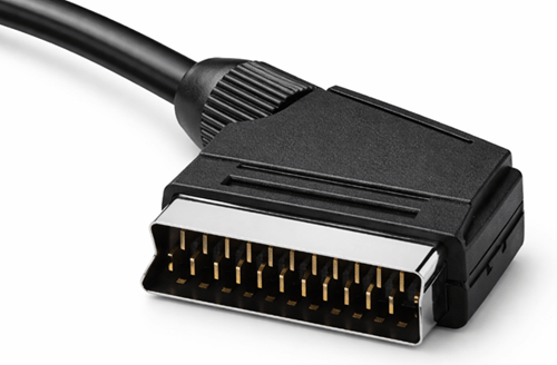
The SCART connector has a wide rectangular body with slightly angled corners that prevent incorrect insertion. This keyed shape allows the plug to fit into the socket in only one orientation, reducing the risk of misalignment during connection.
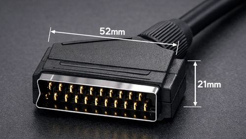
The connector is larger than modern audio-video interfaces, measuring about 52 mm wide and 21 mm high. Inside the housing are 21 metal contacts arranged in two staggered rows, with each pin assigned to a specific audio, video, or control signal. Connectors often use nickel-plated or gold-plated contacts to improve conductivity and resist corrosion.
The cable is typically covered with a flexible PVC jacket that protects the internal conductors. Higher-quality SCART cables may include individual shielding for signal wires, molded connectors with strain relief, and thick insulation to reduce electromagnetic interference. These features help maintain stable audio and video transmission.
SCART Pin Layout
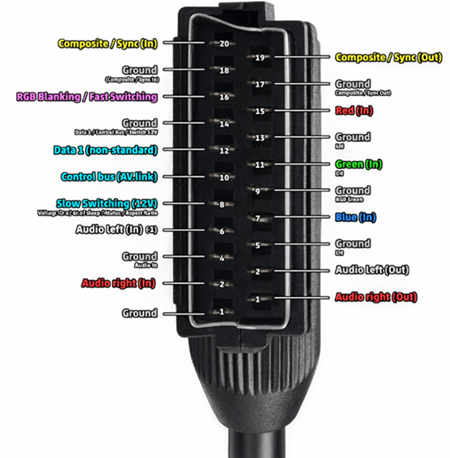
The SCART interface uses 21 pins, each assigned to a specific signal or function. This layout allows audio, video, and control signals to travel through a single cable.
Ground pins are placed between signal pins to reduce interference and improve signal isolation.
| Pin | Signal Type | Function |
|---|---|---|
| 1 | Audio Output (Right) | Right audio channel output |
| 2 | Audio Input (Right) | Right audio channel input |
| 3 | Audio Output (Left) | Left audio channel output |
| 4 | Audio Ground | Ground reference for audio |
| 5 | Blue Ground | Ground for blue video |
| 6 | Audio Input (Left) | Left audio channel input |
| 7 | Blue | Blue component of RGB video |
| 8 | Status / Switching | Input selection and aspect ratio control |
| 9 | Green Ground | Ground for green video |
| 10 | Data Bus | AV.link communication |
| 11 | Green | Green component of RGB video |
| 12 | Data Bus | AV.link communication |
| 13 | Red Ground | Ground for red video |
| 14 | Data Ground | Ground for data communication |
| 15 | Red | Red component of RGB video |
| 16 | Fast Blanking | RGB switching signal |
| 17 | Video Ground | Ground for composite video |
| 18 | Blanking Ground | Ground for switching signals |
| 19 | Composite Output | Composite video output |
| 20 | Composite Input | Composite video input |
| 21 | Shield | Connector casing ground |
Because the interface supports both input and output signals, connected devices can exchange audio, video, and control information.
SCART Signal Types
SCART carries several kinds of signals through one connector, allowing audio, video, and basic device control to work together through a single cable.
Video Signals
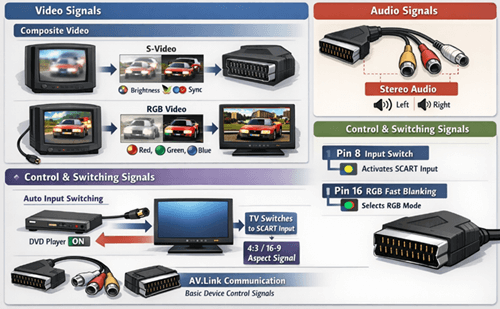
SCART supports several analog video formats:
• Composite video
• RGB video
• S-Video (supported by some devices with compatible wiring)
Composite video combines brightness, color, and synchronization into one signal. It is simple to transmit, but it can produce color interference and lower picture clarity. S-Video separates luminance and chrominance, which improves image sharpness compared with composite video. RGB keeps red, green, and blue signals separate, producing a clearer and more accurate image. Many retro game consoles and DVD players achieve their best analog picture quality through RGB SCART connections.
Audio Signals
SCART also carries stereo analog audio, allowing the left and right sound channels to travel alongside video through the same cable. This reduces cable clutter and removes the need for separate audio leads in many setups.
Control and Switching Signals
In addition to audio and video, SCART includes control lines that allow connected devices to trigger automatic functions on the television. One common feature is automatic input switching. When a connected device such as a DVD player powers on, the TV can detect the signal and change to the correct SCART input without manual selection.
Two pins are central to this process:
| Pin | Function |
|---|---|
| Pin 8 | Input switching voltage |
| Pin 16 | RGB fast blanking signal |
Pin 8 sends a voltage signal that tells the television a connected device is active. This can trigger automatic source selection and can also signal whether the display should use a 4:3 or 16:9 aspect ratio. Pin 16 tells the television whether the incoming signal is RGB or composite, allowing it to switch to the proper display mode.
SCART also supports AV.link, a simple communication system that lets devices exchange basic commands and status information. This made coordinated device control possible in older home entertainment systems and introduced ideas later seen in HDMI-CEC.
Types of SCART Cables
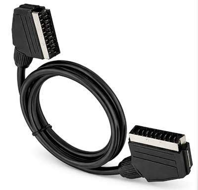
• Fully Wired SCART – All 21 pins connected, allowing RGB video, composite video, stereo audio, and control signals
• Composite SCART – Only composite video and stereo audio are wired. This type is common for basic connections but does not support RGB
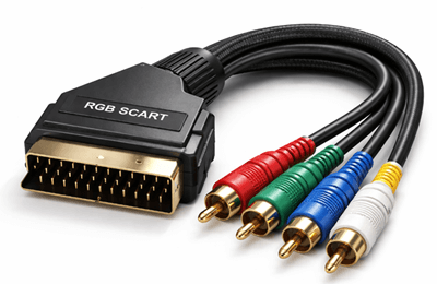
• RGB SCART – Designed for RGB video transmission, producing higher picture quality when used with compatible devices
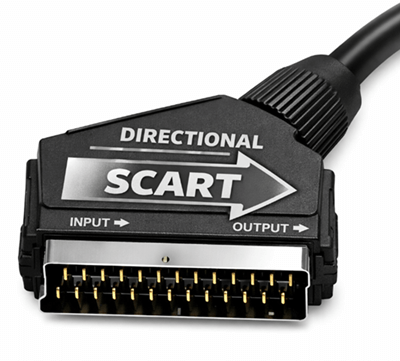
• Directional SCART – Works in one direction only, either as an input or output cable
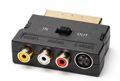
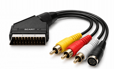
• SCART Adapter – Converts SCART to other interfaces such as RCA or S-Video so older devices can connect to different systems
Common Devices That Use SCART
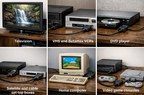
• Televisions – main connection for audio and video input
• VHS and Betamax VCRs – playback and recording connections
• DVD players – standard-definition video output
• Satellite and cable set-top boxes – broadcast receiver connections
• Home computers – video output on some older systems
• Video game consoles – direct audio-video connection to televisions
SCART Compared with Other Analog Video Connectors
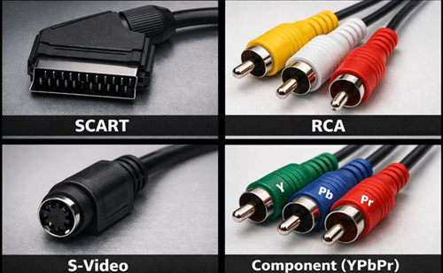
| Connector | Signal Support | Connection Design | Video Quality | Typical Use |
|---|---|---|---|---|
| SCART | Composite video, RGB video, stereo audio, control signals | Single 21-pin connector carrying multiple signals | High for analog when RGB is used | European televisions and home entertainment systems |
| RCA | Composite video and stereo audio | Separate plugs for video and audio connections | Lower than RGB or component | VCRs, DVD players, and general AV devices |
| S-Video | Separated luminance (Y) and chrominance (C) | 4-pin connector dedicated to video only | Better than composite but lower than RGB | DVD players and some video equipment |
| Component (YPbPr) | Analog component video | Three separate video connectors | Higher analog video quality and supports higher resolutions | HDTVs and later analog video equipment |
Unlike RCA connectors, SCART carries multiple signal types through one connector, reducing cable clutter.
SCART vs HDMI Comparison
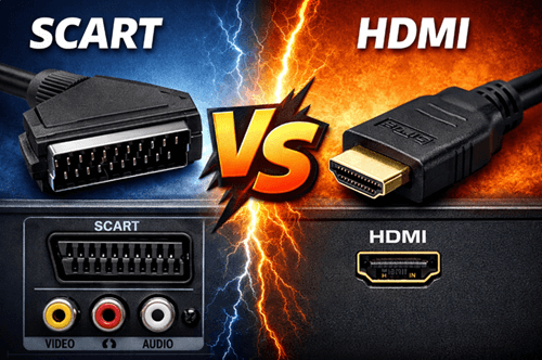
| Feature | SCART | HDMI |
|---|---|---|
| Signal Type | Analog | Digital |
| Resolution Support | Standard Definition (SD) | Up to 8K |
| Audio Support | Stereo analog | Multichannel digital |
| Image Quality | Limited by analog transmission | Supports modern digital formats |
| Extra Features | Basic switching and control signals | HDR, HDCP, surround sound |
| Typical Use | Older TVs and AV devices | Modern TVs and media systems |
SCART to HDMI Conversion
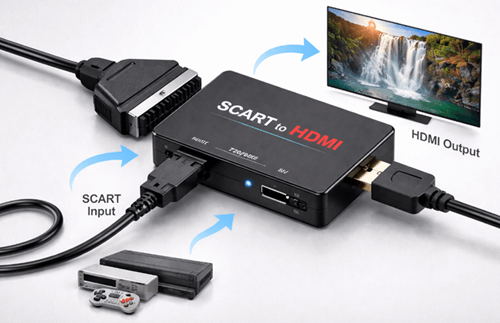
| Aspect | Description |
|---|---|
| Purpose | Connect SCART devices to HDMI televisions |
| Conversion Type | Converts analog SCART signals into digital HDMI output |
| Additional Functions | Some converters upscale video to 720p or 1080p |
| Quality Limitation | Original signal quality cannot be improved |
| Possible Drawbacks | Low-quality converters may introduce input lag |
Troubleshooting Common SCART Problems
| Problem | Possible Cause |
|---|---|
| No picture | Incorrect input selection or faulty cable |
| Black-and-white image | Incorrect S-Video or composite configuration |
| Poor picture quality | Composite video used instead of RGB |
| No audio | Incorrect pin wiring or adapter problem |
| Intermittent signal | Loose connector or damaged cable |
The Role of SCART in Legacy and Retro Systems
SCART continues to play a role in legacy video equipment and retro gaming setups even though it is no longer included in most modern consumer electronics. Many older televisions, VCRs, DVD players, set-top boxes, and game consoles were designed around SCART connections, so the interface remains useful for maintaining compatibility with these systems.
You can often prefer RGB SCART connections because they deliver a sharper and more stable image than composite video. To connect these older devices to modern displays, users often rely on SCART scalers, converters, or upscalers that convert analog signals into HDMI while preserving the original image characteristics as much as possible.
Although HDMI has replaced SCART in modern equipment, the connector still helps bridge older analog hardware with current display technology while preserving the original viewing experience of classic media and games.
Conclusion
Although modern devices rely on digital interfaces such as HDMI, SCART remains a key part of analog audio-video history. Its ability to carry multiple signals through a single connector helped standardize home entertainment connections for many years. Today, it continues to support retro equipment and legacy systems, preserving compatibility between classic devices and modern displays.
Frequently Asked Questions [FAQ]
Why was SCART mainly used in Europe?
SCART became common in Europe because it was standardized by European electronics regulations and widely adopted by television manufacturers in the region. Many European TVs included SCART ports by default, which encouraged device makers such as VCR and DVD player manufacturers to support the connector for compatibility with local television systems.
Can SCART transmit high-definition video signals?
No. SCART was designed for standard-definition analog television systems such as PAL and NTSC. It does not support modern high-definition or ultra-high-definition video formats. The interface can carry high-quality analog RGB signals, but its resolution capabilities remain limited to standard-definition video.
Do all SCART cables support RGB video?
No. Only fully wired SCART cables or cables specifically designed for RGB transmission support RGB video signals. Some inexpensive SCART cables only carry composite video and stereo audio, which results in lower picture quality compared with RGB connections.
How long can a SCART cable be without losing signal quality?
Most SCART cables perform best when kept under about 2 to 3 meters. Longer cables may introduce signal loss, interference, or reduced picture clarity because analog video signals weaken over distance. High-quality shielded cables can reduce these effects but cannot eliminate them entirely.
Why do some SCART connections show only black-and-white video?
A black-and-white image often occurs when the television and source device are using different video formats, such as S-Video and composite. If the wiring or adapter does not properly support the selected format, the color signal may not be transmitted correctly, leaving only the brightness information visible.


