


Hysteresis loss in a transformer is the energy turned into heat in the core as the AC magnetic field flips and the magnetic domains move around the B–H loop each cycle. It depends on material, frequency, flux level, and temperature. This article explains causes, core materials, equations, system effects, testing, modeling, and ways to reduce hysteresis loss in detail.

Hysteresis Loss in a Transformer
Hysteresis loss in a transformer is the electrical energy that turns into heat inside the magnetic core each time the AC voltage changes direction. As the current goes positive and negative, the magnetic field in the core also flips back and forth. The tiny magnetic regions inside the core must move and realign during every cycle, and this motion is not perfectly smooth. Because of this, some energy is lost as heat every time the field reverses.
This loss is present even when the transformer is unloaded, so it still draws power and wastes energy. Hysteresis loss lowers transformer efficiency, adds to no-load power use, and raises core temperature. The level of hysteresis loss affects core size, the choice of core materials, and how much cooling is required to keep the transformer operating safely.
Magnetic Domains and Hysteresis Loss
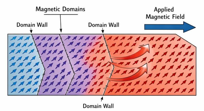
Inside the magnetic core of a transformer, the material is made up of many tiny regions called magnetic domains. The boundaries between domains are called domain walls. These walls do not move freely, because they are held back by imperfections inside the material. Each time the AC field changes direction, extra energy is needed to move these domain walls. That extra energy is turned into heat in the core and becomes part of the hysteresis loss in the transformer.
B–H Loop and Hysteresis Loss in Transformer Cores
The B–H loop is a graph that shows how the magnetic flux density B in a transformer core changes when the magnetic field strength H goes through one full AC cycle. As the AC current rises, falls, and reverses, the point on this graph moves around a closed loop instead of following a single straight line. The shape and size of this loop tell how the core behaves and how much energy is lost as heat because of hysteresis.
Basic Parts of the B–H loop
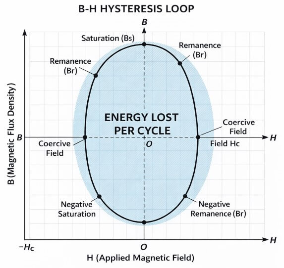
• Saturation region: When H is very high, B barely increases, which means the core is saturated.
• Remanence (Br): When H returns to zero, B is not zero, showing the core keeps some magnetization.
• Coercive field (Hc): This is the reverse value of H needed to bring B back down to zero.
• Loop area: The area inside the loop stands for the energy lost in the core during each cycle; a larger area means higher hysteresis loss.
Steinmetz Equation for Hysteresis Loss
Ph = kh f B nmax V
| Symbol | Meaning |
|---|---|
| (*Ph*) | Hysteresis loss (W) |
| (*kh*) | Constant that depends on the core material |
| (*f*) | AC frequency (in hertz, Hz) |
| (*B nmax*) | Maximum flux density in the core (in tesla, T) |
| (*n*) | Steinmetz exponent (typically > 1) |
| (*V*) | Core volume (m³) |
Transformer Core Materials and Hysteresis Loss
Grain-oriented silicon steel
• Has a narrow hysteresis loop in one main direction
• Gives lower hysteresis loss along that direction at power-line frequency
Non-oriented electrical steel
• Has more uniform magnetic properties in all directions
• Shows slightly higher hysteresis loss but works well when flux changes direction in the core
Ferrites (MnZn, NiZn)
• Have very low hysteresis and eddy current losses at high frequency
• Help keep hysteresis loss smaller in high-frequency transformers
Amorphous and nanocrystalline alloys
• Have very narrow hysteresis loops
• Provide very low hysteresis loss for energy-efficient operation
These materials are especially important in high-frequency transformers, discussed in Section 9.
Operating Conditions that Influence Hysteresis Loss
Frequency
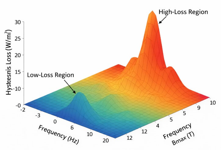
As frequency increases, the magnetic field in the core flips direction more times each second. Each flip causes some energy loss, so more flips per second mean greater hysteresis loss.
Peak flux density (Bmax)
A higher Bmax makes the loop area larger, which increases hysteresis loss and can bring the core closer to saturation.
Temperature
Temperature changes how easily magnetic domains move inside the core. Depending on the material, core loss can increase or decrease with temperature, so data from the material is needed to know how hysteresis loss behaves.
Hysteresis Loss vs. Other Transformer Losses
| Loss type | Where it happens | Main cause | Depends mainly on |
|---|---|---|---|
| Hysteresis | Core | Magnetic domains realigning every AC cycle | Frequency, peak flux*B**max*, core material |
| Eddy current | Core | Currents induced in the metal core by changing flux | Frequency²,*B**max*², core thickness |
| Copper (I²R) | Windings | Current flowing through resistance in the wire | Load current, wire resistance |
| Stray/leakage | Core/air space | Magnetic flux that does not link all windings | Core shape, spacing, and layout |
System-Level Effects of Hysteresis Loss in Transformers
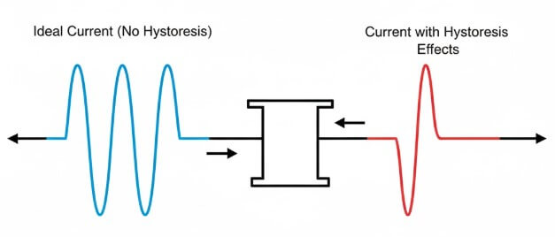
Hysteresis loss in a transformer also changes how it behaves in the electrical system. It causes higher no-load power use, so the transformer draws more power from the supply even when it is not feeding any load. The magnetizing current becomes distorted and less like a smooth sine wave, which makes its shape more uneven. This uneven current adds extra frequency components called harmonics, which increases harmonic content and total harmonic distortion (THD) in the system. At the same time, a larger part of the current becomes reactive instead of useful, which lowers the power factor and means less of the current is doing real work.
Hysteresis Loss in High-Frequency Transformer Cores
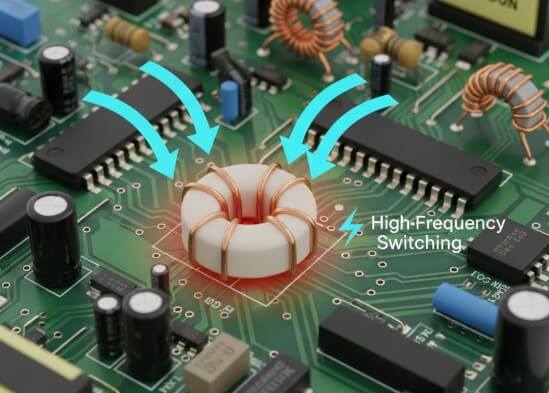
In many modern circuits, transformers are small parts mounted on a printed circuit board and work at high frequencies, often in the tens or hundreds of kilohertz. At these higher frequencies, hysteresis loss in the core becomes more important, because the magnetic field in the core is changing direction many times each second. Ferrite cores are used in this case, since they help keep hysteresis loss and eddy current loss lower at high frequency.
The maximum flux density, often written as Bmax, is carefully limited so the core loss stays within safe levels, and the core does not overheat. Core loss curves provided for the material are used to estimate how much total core loss, including hysteresis loss, will occur at a given frequency and flux level. Because these transformers sit close to other parts on the circuit board, the heat from hysteresis loss affects local temperature and can influence how reliably nearby components operate.
Modeling Hysteresis Loss in Circuit Simulation
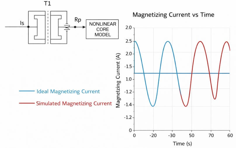
In circuit simulation, hysteresis loss in a transformer core is represented with simple models that still capture the main effects. One basic method is to use a resistor in parallel with the magnetizing inductance, so that this resistor represents the power lost as heat in the core at a chosen operating point. More advanced models use non-linear B–H curves, such as Jiles–Atherton or Preisach models, which follow the real shape of the hysteresis loop and make time-domain results more accurate.
Another common method is to use Steinmetz-based behavioral blocks, where the core loss is calculated from the flux waveform using Steinmetz-type equations and then added into the circuit as a power-dissipating element. These approaches help show how hysteresis loss affects current, voltage, and heating in a simulated transformer.
Measuring Hysteresis Loss in Transformer Cores
Material tests (Epstein frame or single sheet)
A strip or sheet of core material is placed in a special test setup and driven with a known AC field. The B–H loop is recorded, and the core loss per unit volume is calculated.
Toroidal core test
A winding is placed on a ring-shaped (toroidal) core and supplied with a chosen voltage and frequency. The input power is measured, and the winding I²R loss is subtracted to find the total core loss, which includes hysteresis loss.
Open-circuit transformer tests
The primary winding of a transformer is energized at its rated voltage while the secondary is left open. The power drawn from the source is mostly core loss, which is the sum of hysteresis loss and eddy current loss.
Frequency and voltage sweep
The test is repeated at different frequencies and voltage levels. Watching how the measured loss changes help show when hysteresis loss is more required and when eddy current loss becomes a larger part of the total.
Conclusion
Hysteresis loss comes from repeated movement of magnetic domains as the core cycles around its B–H loop, turning part of the input power into heat even at no load. Its size depends on core material, frequency, flux density, and temperature. With proper modeling, measurement, and material and design choices, hysteresis loss can be limited and controlled.
Frequently Asked Questions [FAQ]
How does hysteresis loss affect transformer life?
It keeps the core hotter for long periods, which speeds up insulation aging and can shorten the transformer’s service life.
How is hysteresis loss linked to inrush current?
Because of the B–H loop and leftover magnetization, the core can go near saturation at switch-on, causing a very high inrush current for a short time.
Does core shape change hysteresis loss?
Yes. Toroidal cores have lower hysteresis loss than E–I cores because the magnetic path is smoother and more uniform.
How does hysteresis loss affect energy cost in always-on transformers?
It acts as a constant no-load power draw, increasing yearly energy consumption and cooling needs even when output power is low.
Can stress or aging increase hysteresis loss?
Yes. Mechanical stress, vibration, and repeated heating and cooling can disturb the core structure, widen the B–H loop, and raise hysteresis loss over time.


