


HRC fuses protect electrical systems from dangerous overcurrent and fault conditions. They are designed for fast, reliable operation that helps reduce equipment damage and improve circuit safety. This article explains how HRC fuses work, how they are built, their main types, and how to select and maintain them effectively.
What Are HRC Fuses?
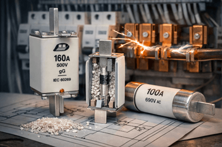
A High Rupture Capacity (HRC) fuse is an electrical protection device that disconnects a circuit safely when excessive current flows, especially under high fault conditions. It contains a fusible element inside a heat-resistant casing. When current rises above a safe level, the element melts and opens the circuit, helping protect wiring, equipment, and connected systems from damage.
Working Principle of HRC Fuses
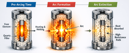
HRC fuses operate by heating, melting, and interrupting current in a controlled way when current rises above a safe level. Under normal conditions, the fuse element carries current without opening the circuit. When overcurrent or fault current occurs, the element begins to heat.
The first stage is called pre-arcing time. During this period, the fuse element absorbs energy until it reaches its melting point. The higher the fault current, the faster this stage occurs. After the element melts, an arc forms between the separated ends. The quartz filler surrounding the element helps extinguish this arc by absorbing heat and forming a high-resistance path that stops current flow.
Because of this fast interruption process, an HRC fuse can limit the fault current before it reaches its highest peak. This operating method helps the fuse disconnect the circuit safely during severe fault conditions.
Construction of HRC Fuses
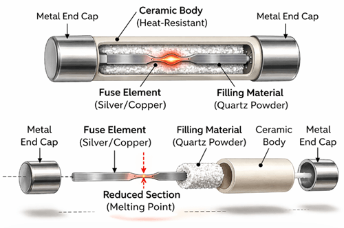
An HRC fuse is built with a strong, heat-resistant body, usually made of ceramic, so it can withstand high temperature and mechanical stress. It includes metal end caps for secure connection to the circuit. Inside the fuse, a metal fuse element, often made of silver or copper, carries the current. This element is surrounded by quartz powder or a similar filling material that absorbs heat, suppresses the arc, and supports safe interruption during operation. Some HRC fuses also use specially shaped or reduced sections in the element to control how and where melting occurs.
HRC Fuse Types, Classes, and Standards
NH Type Fuse
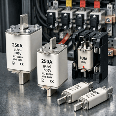
NH (Niederspannungs-Hochleistungs) fuses are a widely used type of HRC fuse for low- and medium-voltage systems. They are known for high breaking capacity, strong construction, and reliable performance in power distribution, motor protection, and industrial installations.
DIN Standard Fuse
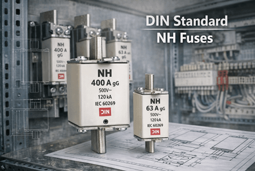
DIN is a standard, not a fuse type. It defines dimensions, ratings, and interchangeability. In practice, many NH fuses are made according to DIN standards.
Key distinction:
• NH → physical fuse design and application type
• DIN → standard that defines size and performance
This standardization improves compatibility across manufacturers and makes replacement easier in switchgear and control panels.
Blade-Type Fuse as a Related Low-Voltage Fuse Form
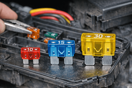
Blade-type fuses use a compact plug-in design with a molded body and metal terminals. They are commonly used in automotive and low-voltage circuits. Although some blade fuses may have relatively high interrupting ratings, they are generally not classified as industrial HRC fuses. They are better understood as a related low-voltage fuse form rather than a main HRC fuse type.
Common HRC Fuse Classes
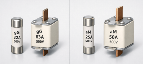
HRC fuses are also classified by their protection range and intended application. Common classes include gG and aM. gG fuses provide full-range protection against both overload and short circuit, which makes them suitable for general-purpose circuit protection. aM fuses provide short-circuit protection only and are often used in motor circuits, where overload protection is handled by a separate device such as an overload relay. These classes help match the fuse more closely to the behavior of the protected circuit.
Applications of HRC Fuses

• Industrial control panels and motor systems – Protect motors, starters, and control equipment from overloads and short circuits
• Power distribution systems and transformers – Help protect feeders, distribution boards, and transformer circuits from fault current damage
• Renewable energy systems such as solar and wind – Used in inverter circuits, combiner boxes, and related power conversion equipment
• Transportation systems, including rail and electric vehicles – Provide circuit protection in demanding systems with high electrical loads
HRC Fuse Selection and Specification Guide
| Factor | Description | Key Consideration |
|---|---|---|
| Rated Current | The current level the fuse can carry under normal conditions | Select slightly above normal operating current to avoid unnecessary operation |
| Rated Voltage | Maximum voltage the fuse can safely handle | Must be equal to or greater than the system voltage |
| Breaking Capacity | Maximum fault current the fuse can safely interrupt | Should exceed the highest possible fault current in the system |
| Time-Current Characteristics | Response behavior under overload or short circuit | Match to the operating profile of the protected circuit |
| Application Requirements | Specific operating conditions of the system | Account for motor starting current, inrush current, or circuit sensitivity |
| Fuse Type and Size | Physical design and dimensions of the fuse | Must match the fuse holder and panel layout |
| Environmental Conditions | Surrounding operating environment | Consider temperature, humidity, dust, and ventilation |
| Compliance Standards | Safety and performance certifications | Ensure the fuse meets required industry and regulatory standards |
HRC Fuse Comparisons
HRC Fuse vs Circuit Breaker
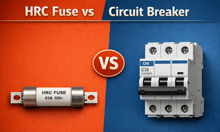
| Feature | HRC Fuse | Circuit Breaker |
|---|---|---|
| Working Principle | Element melts and interrupts current | Trips using thermal, magnetic, or electronic mechanism |
| Operation | Single-use | Resettable |
| Cost | Lower initial cost | Higher initial cost |
| Speed | Very fast and current-limiting | Usually slower than an HRC fuse |
| Current Limiting | Yes | Limited in standard designs |
| Maintenance | Minimal | Requires periodic inspection |
| Function | Protection only | Protection and switching |
| Size | Compact | Larger |
HRC Fuse vs LBC Fuse
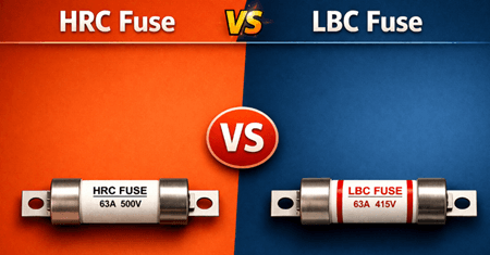
An LBC fuse, or low breaking capacity fuse, is designed for lower fault levels and simpler circuits than an HRC fuse.
| Feature | HRC Fuse | LBC Fuse |
|---|---|---|
| Breaking Capacity | Very high | Limited |
| Construction | Ceramic body with filler | Glass body |
| Arc Control | Strong | Limited |
| Current Limiting | Yes | Minimal |
| Applications | Industrial and power systems | Low-power circuits |
| Reliability | High | Moderate |
Common Problems and Maintenance
| Issue / Maintenance Area | Description | Recommendation |
|---|---|---|
| Frequent Fuse Blowing | Often caused by overload or incorrect rating | Check load conditions and confirm correct fuse rating before replacement |
| Loose Connections | Poor contact can cause overheating and unstable operation | Make sure terminals and connections are tight and secure |
| Incorrect Fuse Selection | Wrong type or rating can cause early operation or weak protection | Choose a fuse that matches system requirements |
| Physical Damage | Cracks, worn terminals, or visible damage can reduce performance and safety | Inspect regularly and replace damaged fuses immediately |
| Environmental Effects | Dust, moisture, and contaminants can reduce performance over time | Keep panels clean, dry, and properly sealed |
| Regular Inspection | Routine checks help identify early signs of failure | Inspect fuses and connections for wear or damage |
| Proper Replacement | Incorrect replacement can weaken protection | Always use the correct type, size, and rating |
| Fault Identification | Replacing a fuse without fixing the cause can lead to repeated failure | Identify and correct the root cause before installing a new fuse |
Future Trends and Developments
HRC fuse technology continues to develop in response to modern electrical systems that require better efficiency, compact design, and improved protection coordination.
• Advanced materials and thermal performance – New fuse element alloys and improved filler materials help improve arc control, reduce energy let-through, and support longer service life under repeated stress
• Integration with monitoring systems – Although fuses remain passive devices, they are increasingly paired with external monitoring modules that detect fuse status, temperature rise, and fault events
• Compact high-performance designs – Ongoing development aims to reduce fuse size while maintaining or improving breaking capacity
• Applications in electrification and renewable systems – HRC fuses are being adapted for solar PV systems, battery storage, and electric vehicles, where fast fault protection is important
• Improved system coordination – Greater focus is placed on selectivity and coordination with relays and circuit breakers so that only the affected section is isolated during a fault
• Compliance with evolving standards – Continued alignment with standards such as IEC 60269 supports consistent performance, safety, and broader compatibility
These developments reinforce the value of HRC fuses in both established and emerging electrical systems.
Conclusion
HRC fuses are a strong choice for circuits that may face high fault current and need fast, dependable protection. They are often preferred over simpler fuse designs when breaking capacity, arc control, and fault limitation are more important. They may also be preferred over circuit breakers in applications where compact size, very fast fault clearing, and low routine maintenance are the main priorities. The best choice depends on the fault level, circuit behavior, coordination needs, and replacement strategy of the system.
Frequently Asked Questions [FAQ]
How do you test if an HRC fuse is still working?
An HRC fuse can be tested with a multimeter set to continuity or resistance mode. A good fuse shows low resistance or continuity, while a blown fuse shows no continuity. Always isolate the circuit and remove the fuse before testing.
What causes an HRC fuse to fail prematurely?
Premature failure is often caused by incorrect fuse rating, frequent inrush current, poor installation, or loose connections. Environmental factors such as high temperature, dust, and moisture can also reduce service life.
Can an HRC fuse be reused after it blows?
No. HRC fuses are single-use devices. Once the fuse element melts, the circuit is permanently opened and the fuse must be replaced.
What is the difference between gG and aM HRC fuse types?
gG fuses provide full-range protection against overload and short circuit, making them suitable for general applications. aM fuses provide short-circuit protection only and are commonly used in motor circuits where overload protection is handled separately.
How do you choose the correct HRC fuse for motor protection?
Choose a fuse that can handle motor starting current without unnecessary operation. Time-current characteristics, inrush current, and coordination with overload relays should all be considered. aM-type fuses are commonly used for motor circuits because they can tolerate short-term starting current better.


