


Brushless DC motors are used because they are efficient, reliable, and need less maintenance than brushed motors. They use electronic commutation instead of brushes, which improves control and reduces wear. Their performance depends on motor design, timing, feedback, control method, drive electronics, speed-torque behavior, and heat limits. This article gives information about all these points.
Brushless DC Motor Basics
What Is a Brushless DC Motor (BLDC)?
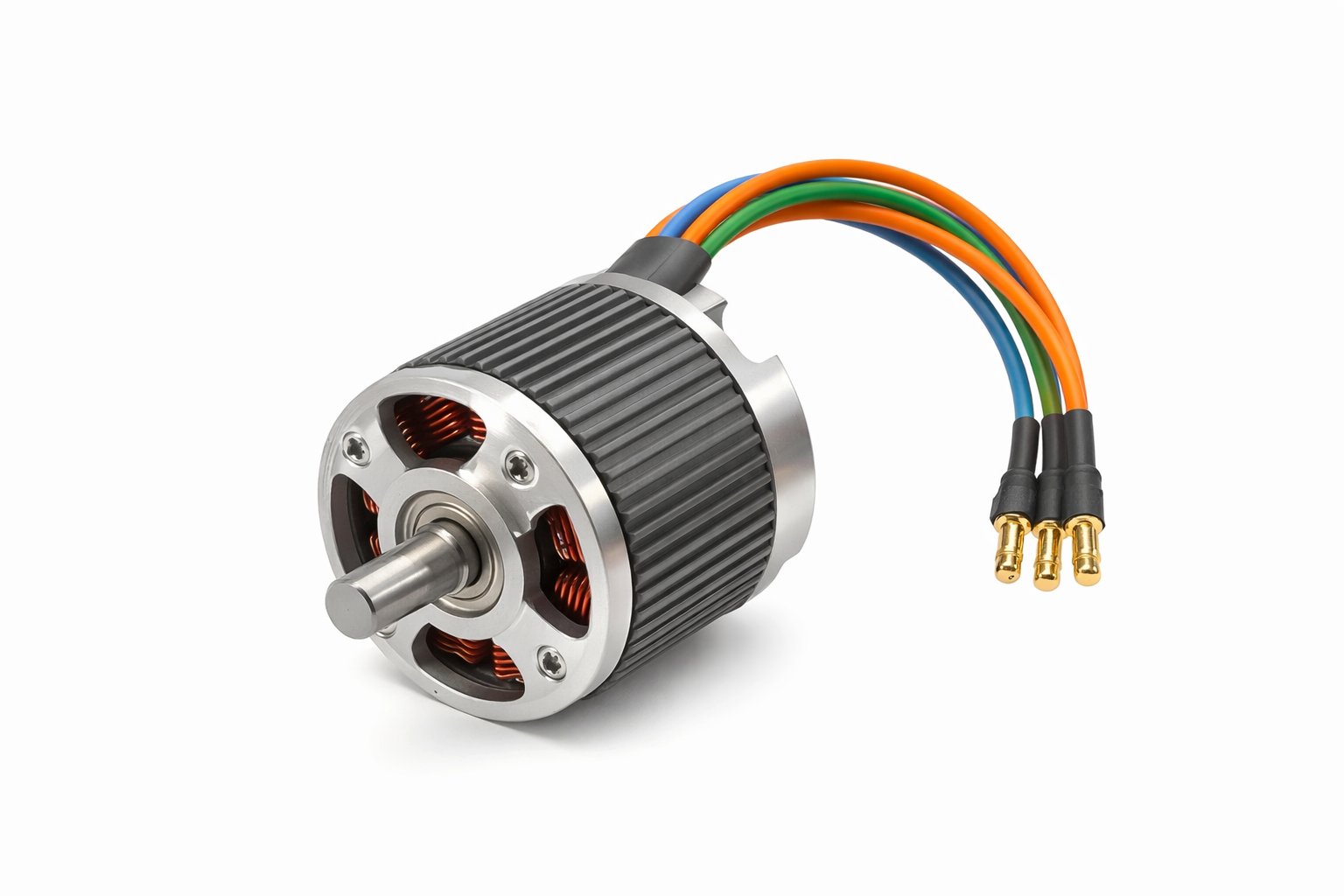
A Brushless DC Motor (BLDC) is a permanent-magnet motor powered by a DC source that runs using electronic commutation rather than brushes and a mechanical commutator. A controller switches current through the stator windings in a planned sequence to create a rotating magnetic field. The rotor contains permanent magnets that follow this rotating field, which produces rotation. Because there are no brushes rubbing on a commutator, mechanical wear is reduced, maintenance is lower, and efficiency is often higher. Speed and torque are controlled by how the controller times the switching and adjusts the voltage and current.
BLDC vs Brushed DC vs PMSM
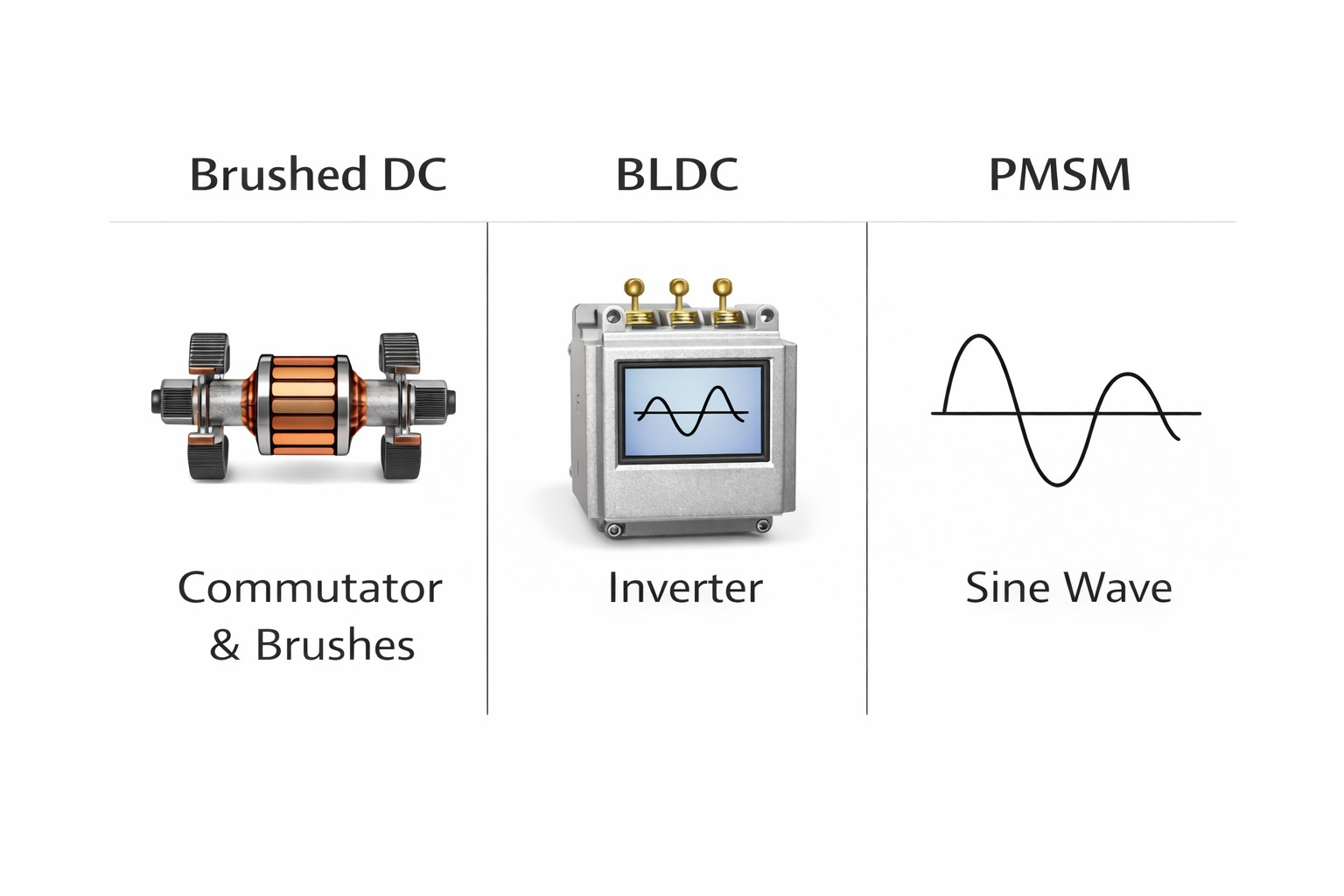
Brushed DC motors use brushes and a commutator to switch current inside the motor, which makes control simple but adds wear parts. BLDC motors remove the brushes and use an electronic controller to switch the stator phases, so commutation is handled electronically. PMSM motors also use permanent magnets and electronic control, so their hardware can look like that of a BLDC motor. The common difference is how the motor’s voltage waveform is shaped and how the controller drives the phases. BLDC systems are often associated with trapezoidal waveforms and step-based commutation, while PMSM systems are often associated with sinusoidal waveforms and smoother control methods.
Electronic Commutation and Switching Timing
Brushless DC Motor Working Basics
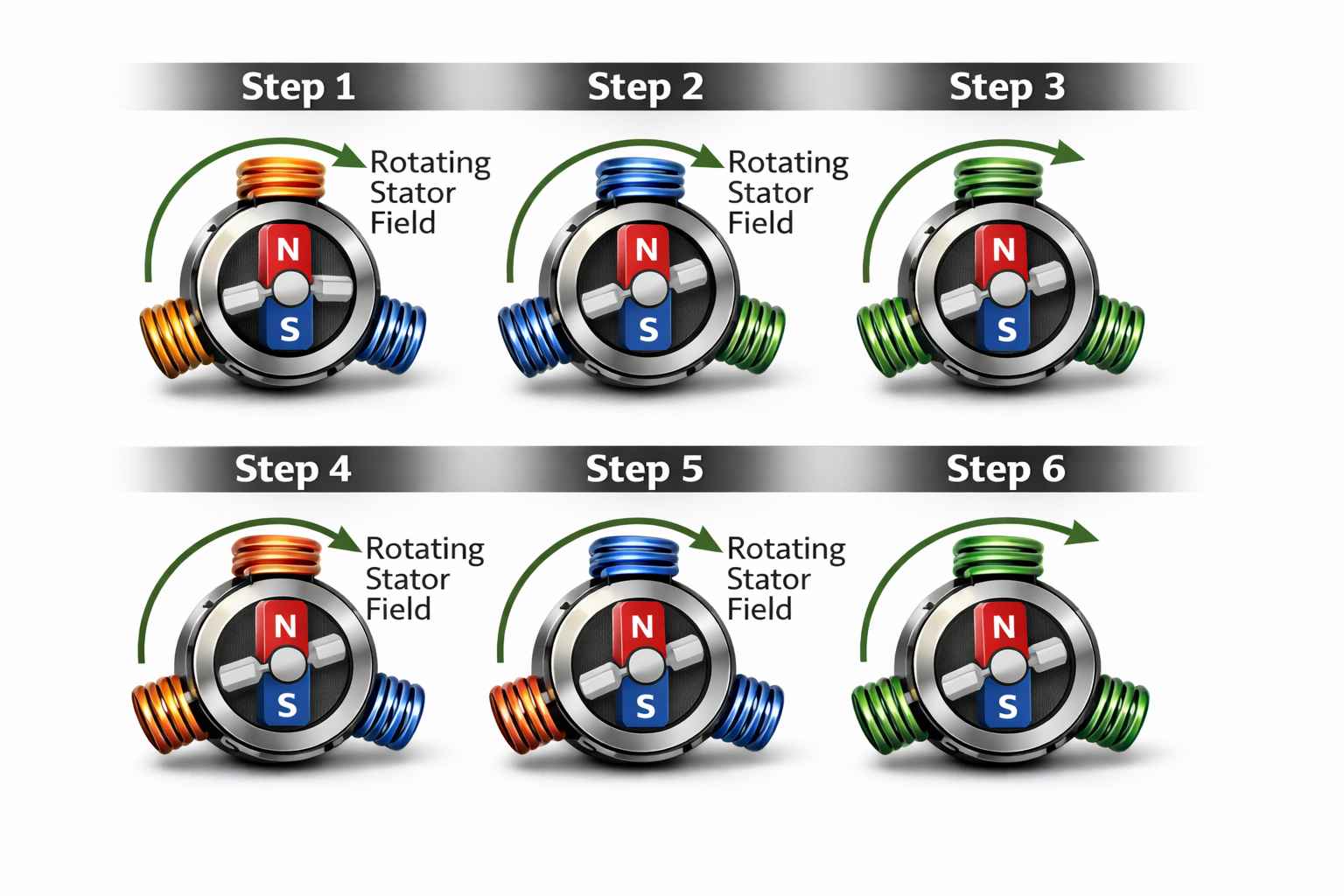
A BLDC motor creates motion when current in the stator windings produces a magnetic field that interacts with the rotor’s permanent magnets. The controller sends current to the windings in a repeating order, so the strongest part of the stator’s magnetic field keeps shifting around the motor. This shifting pattern acts like a rotating magnetic field. As the stator field moves, the rotor magnets keep turning to stay lined up with it. This steady following action is what produces continuous rotation and torque.
Switching Timing and Its Effects
• When switching occurs too early, the stator field leads the rotor position and the torque becomes weaker.
• When switching occurs too late, the stator field lags behind the rotor and torque ripple increases.
• Proper switching timing improves torque efficiency and reduces noise and vibration.
BLDC Motor Construction and Core Components
Core Motor Parts
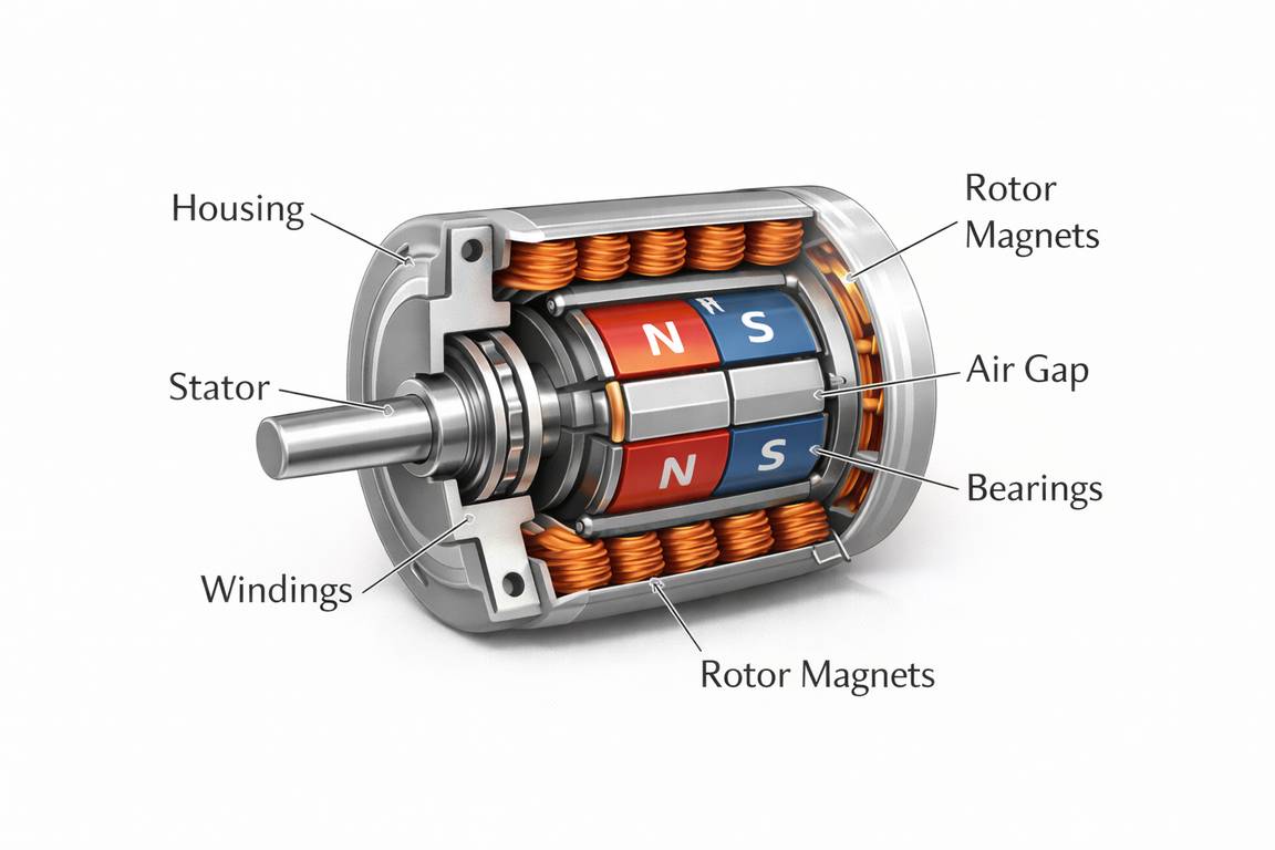
A BLDC motor consists of a stator, a rotor with permanent magnets, an air gap, bearings, and a housing. The stator is made of laminated steel and carries multi-phase windings that generate the rotating magnetic field. The rotor contains permanent magnets that follow this rotating field to produce motion. The air gap between stator and rotor affects magnetic coupling, torque density, and smooth operation. Bearings support the shaft and influence friction, vibration, and service life. The housing keeps the assembly aligned and helps remove heat from the motor.
Rotor Design Factors
Rotor design influences torque, speed behavior, and mechanical strength. Pole count determines the relationship between electrical commutation and mechanical rotation; more poles improve low-speed torque but require faster electrical switching. Magnet placement also affects performance. Surface-mounted magnets are common and simple, while interior magnets provide better mechanical retention at higher speeds. Magnet material determines magnetic strength and temperature stability, influencing torque capability and reliability.
Winding Connections: Star (Wye) vs Delta
The stator windings in a BLDC motor are commonly connected in star (wye) or delta form.
| Connection | Practical effect (typical) | What it supports |
|---|---|---|
| Star (Wye) | Higher torque per volt at lower speed | Stronger low-speed operation on a limited voltage |
| Delta | Higher speed potential on the same voltage | Higher RPM when the torque demand is lower |
Rotor Position Detection and Feedback Options
Why the Drive Needs Rotor Position?
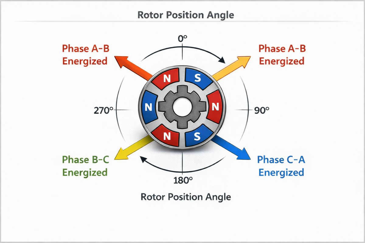
The controller must know the rotor’s position (or estimate it) so it can energise the correct phases at the correct time. Without rotor position information, commutation timing drifts, torque falls, and heating rises during startup and low-speed operation.
Hall Sensors vs Encoders vs Sensorless BLDC
• Hall sensors: affordable and reliable for basic commutation and strong startup torque.
• Encoders/resolvers: used when accurate speed/position control is required.
• Sensorless (back-EMF based): fewer wires/parts, but harder at very low speed and startup due to weak back-EMF.
BLDC Commutation and Control Methods
Commutation Styles: 6-Step vs Sinusoidal / FOC
| Method | What the controller does | Result |
|---|---|---|
| 6-step (trapezoidal) | Switches phases in discrete steps | Simple and robust; more ripple/noise possible |
| Sinusoidal / FOC | Drives smooth phase currents using vector control | Smoother torque; often quieter and efficient over a wide range |
When 6-Step Makes Sense vs When FOC Is Better
Both methods work well, but they are chosen for different goals.
• The 6-step is often chosen when simplicity, cost, and ruggedness matter.
• FOC is chosen when smooth torque, low noise, and precise control matter across a wide speed range.
Electronics of the BLDC Drive System
Three-Phase Inverter Bridge
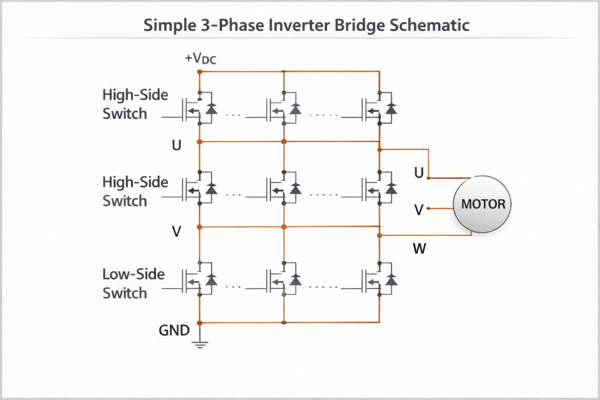
A BLDC motor needs an electronic drive to perform commutation. The power stage is a three-phase inverter made of six switches. By switching these devices in the correct sequence, the drive routes DC power into the motor phases and produces a rotating stator field.
Controller Roles
• Power switches: MOSFETs at many BLDC voltage ranges.
• Gate driver + protections: safe switching, dead-time control, and fault handling.
• Control logic (MCU/DSP): commutation timing, PWM control, sensor reading, and limit management.
Speed, Torque, and Braking in Brushless DC Motors
Speed and Torque Control: PWM and Current Limits
Speed control: PWM duty cycle changes the effective DC voltage to the motor, which changes its speed.
Speed loop: The controller compares the target speed with the measured or estimated speed and corrects the output if there is an error.
Torque and current: Motor torque is closely related to phase current, so limiting current also limits torque.
Current limiting: The drive monitors current and reduces PWM when needed to prevent damage during starts, stops, and sudden load changes.
Direction Reversal and Braking/Regeneration Basics
• Direction reversal: The motor can run in the opposite direction by reversing the commutation order, which changes the phase sequence.
• Braking: The drive can apply torque opposite to the direction of motion to slow the rotor in a controlled way.
• Regeneration: When braking under the right conditions, the motor can act as a generator and send energy back to the DC bus.
Direction control, braking, and regeneration all come from how the drive switches the motor phases and manages current. By changing the commutation sequence and controlling torque, the same BLDC motor can run forward or reverse, slow down smoothly, and in some systems, return part of its energy to the supply.
Performance and Limits of Brushless DC Motors
How do speed and torque behave in a BLDC motor?
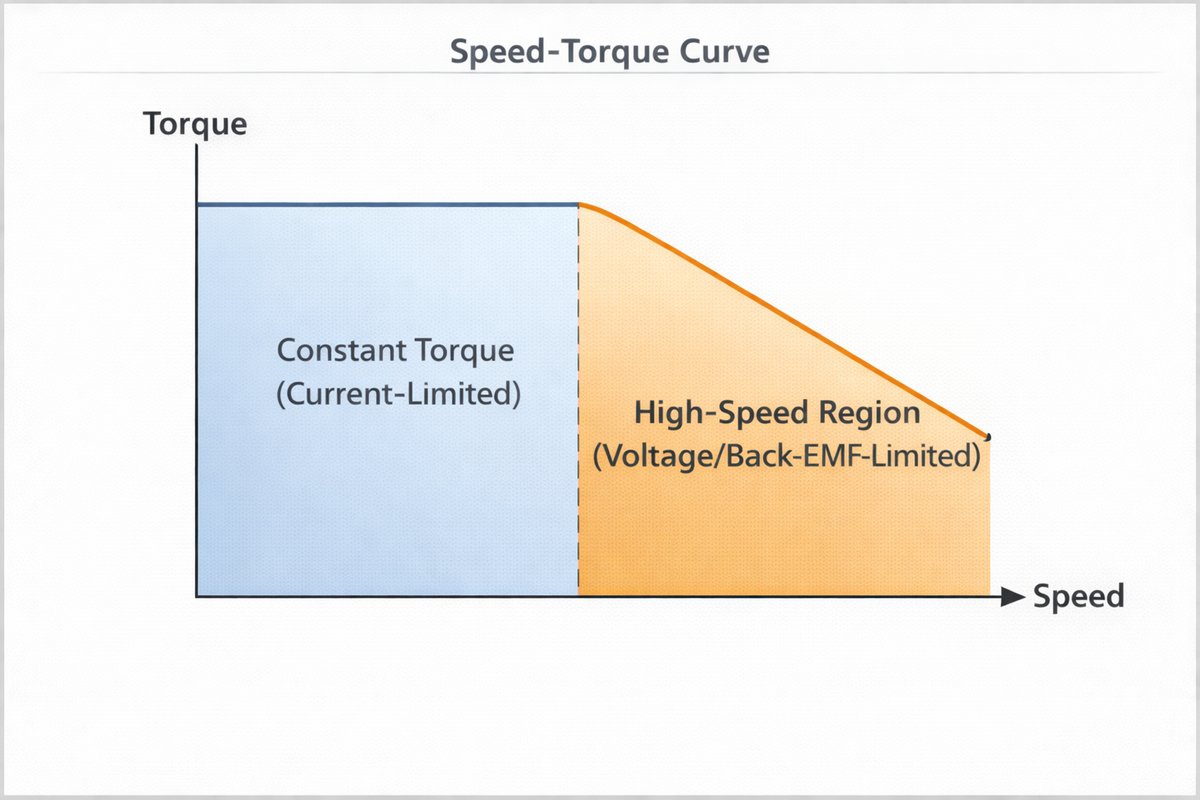
A brushless DC motor does not give the same torque at every speed. At low speed, torque is limited by the drive's current capacity. At higher speeds, the motor reaches a point where the DC bus voltage and back-EMF limit how much torque the drive can produce. On a speed–torque curve, this shows up as a flat region of almost constant torque at lower speeds and a falling torque region at higher speeds.
What factors set the top speed of a BLDC motor?
• DC bus voltage: A higher DC bus voltage gives more voltage headroom to overcome back-EMF at high speed.
• Back-EMF (Ke/Kv): Back-EMF increases with speed and reduces the voltage the drive can use to push current into the windings.
• Control method: Different control methods affect how well the drive maintains torque as speed increases.
• Thermals: Losses in the windings and electronics increase with speed and load, limiting how long the motor can run at high speed.
Specs That Matter Most for Brushless DC Motors
| Spec term (catalog) | What does it tell you | Why it matters |
|---|---|---|
| Rated voltage / DC bus range | Normal supply voltage range | Sets possible speed range and helps pick the right drive |
| Rated current/continuous current | Current that is safe for long use | Shows how much heating will occur at a given load |
| Rated power (W) | Output power at a certain point | Helps compare how strong different motors are |
| Rated torque/peak torque | How much turning force the motor can make | Shows how it will handle starting and short overloads |
| Speed (RPM) | Normal operating speed range | Helps match the motor to the gears and to the load |
| Kv / Ke and Kt constants | Links speed, voltage, and torque | Connects voltage and current to real motor performance |
| Efficiency | How much input power becomes mechanical power | Affects heating, battery life, and running costs |
Efficiency, Losses, and Heat in Brushless DC Motors
Loss sources in a brushless DC motor
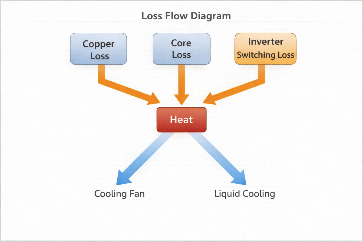
In a brushless DC motor system, not all of the input power is converted into useful mechanical output. Some of it turns into heat inside the motor and drive. Most of this heat comes from copper loss, core loss, and switching loss, and these losses grow when current and speed increase.
• Copper loss (I²R): Copper loss happens in the stator windings and increases with current. Higher torque requires higher current, so copper loss increases as torque demand rises.
• Core or iron loss: Core loss is linked to the changing magnetic field in the stator. It increases with electrical frequency and flux level, so it becomes more required at higher speeds.
• Switching loss: Switching loss occurs in the power electronics that drive the motor. It depends on PWM frequency, the type of switching devices, and the current flowing during each switching event.
Cooling and thermal protection in BLDC systems
Thermal control is needed to keep both the motor and inverter within safe operating limits. Heat should be removed through a thermally conductive mounting path and adequate airflow, while current limits should be set conservatively when cooling is restricted or long operating periods are expected. Temperature sensing and thermal rollback can further protect the system by reducing current when temperatures become excessive, improving reliability and service life.
Applications of Brushless DC Motors
Common applications of brushless DC motors
• Fans and blowers for moving air
• Pumps for moving liquids
• Power tools and small machinery
• Automation and motion systems
• Robotic joints and actuators
• Battery-powered vehicles and devices
Conclusion
Brushless DC motors operate by combining permanent magnets with electronic control to produce smooth, efficient motion. Their actual performance depends on correct commutation timing, rotor position feedback, control method, inverter operation, cooling, and proper motor-drive matching. Speed, torque, efficiency, and reliability are all affected by these factors. Understanding them helps explain how BLDC systems operate, their limits, and what affects long-term performance.
Frequently Asked Questions [FAQ]
How does a sensorless BLDC motor start from standstill?
It starts by forcing the rotor into a known position, then running the motor in open loop. Once the motor reaches enough speed for back-EMF detection, the controller switches to normal sensorless operation.
What causes noise and vibration in a BLDC motor?
Noise and vibration are caused by rotor imbalance, misalignment, worn bearings, cogging torque, uneven air gaps, and PWM switching.
How does load inertia affect a BLDC motor?
High load inertia makes the motor slower to accelerate and decelerate. It also increases torque demand and can raise current during rapid speed changes.
What power supply and wiring points matter in a BLDC system?
The power supply must handle peak current without a voltage drop. Capacitors must smooth switching spikes, and wiring must be properly sized, short, and well grounded to reduce noise.
What protection functions are used in BLDC drives?
BLDC drives use overcurrent, overvoltage, undervoltage, short-circuit, stall, and overtemperature protection to prevent damage.
How do environmental conditions affect a BLDC motor?
Dust, moisture, heat, vibration, and corrosive conditions can reduce performance, damage parts, and shorten motor life.


